

Cold Plate Cooling Systems: Design, Optimization, and Application in High Density Electronics
Cold Plate Cooling Systems: Design, Optimization, and Application in High Density Electronics
Building on our comprehensive exploration of liquid cooling systems in our earlier blog, this edition focuses on the most critical and performance defining component within these systems: the cold plate.
Cold plate cooling systems are revolutionizing how high-performance electronics manage heat in demanding environments. In this guide, we take a deep dive into the design, performance, and applications of liquid cold plates, which are essential for thermal management in industries like data centers, telecommunications, aerospace, and defense.
Liquid cold plates act as high-efficiency heat exchangers, using precision microchannels to direct coolant across critical components. This allows them to remove heat faster and more evenly than traditional air-cooled systems—making them ideal for modern electronics where power density is high and space is limited.
By delivering localized cooling right at the source, cold plates help maintain safe temperatures for processors, GPUs, memory modules, and other high-density electronic devices, even under heavy workloads. As devices continue to shrink while generating more heat, cold plates have become essential for maintaining long-term thermal performance and system reliability.
In a typical setup, cold plates transfer heat from the electronic component into a flowing liquid coolant. The heated coolant is then pumped to a remote heat exchanger, where it releases thermal energy either to the surrounding air or into a secondary cooling loop. This closed-loop cooling architecture supports both targeted heat removal and improved system-level energy efficiency.
Importantly, cold plates contribute to improving data center energy metrics such as Power Usage Effectiveness (PUE). With modern data centers targeting a PUE of less than 1.3, advanced liquid cooling strategies such as the utilization of cold plates are essential to achieve such efficiency benchmarks. There are different designs of cold plates that rely on either single phase or two-phase cooling fluids and the design can be optimized for a specific cooling fluid to maximize heat removal from heat sources.
How does it work?
Cold plates are the foundation of today’s most effective liquid cooling systems. Unlike traditional air cooling, which depends on bulky heatsinks and fans to transfer heat through convection, cold plates use a closed-loop liquid cooling approach. This method draws heat directly away from high-power components such as CPUs, GPUs, memory modules, and power electronics with much greater efficiency.
The key to their performance lies in the circulation of coolant through precision-engineered microchannels built into the cold plate. As the fluid flows beneath the heat-generating device, it absorbs thermal energy and carries it to a remote heat exchanger for safe dissipation. This direct liquid-to-surface contact provides faster, more uniform heat removal—resulting in tighter temperature control, improved system reliability, and longer lifespan for electronic components.

Figure 1. (Cold plate model)
A typical cold plate consists of two main structural components:
The base, which includes the machined or molded microchannel heat exchanger, and
The top cover, which encloses the fluid channels and integrates the inlet/outlet connectors.
These two components are permanently joined using a process (e.g., brazing, diffusion bonding, welding) optimized for the chosen material, usually aluminum, copper, or advanced composite alloys. This joint must remain liquid tight throughout the system’s service life, even under pressure, vibration, or temperature cycling.

Figure 2. [Cold plate design]
Tubing is connected to the fluid ports in the top cover, enabling inlet and outlet flow paths for coolant circulation through the internal channels.
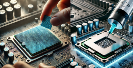
The cold plate base is designed to make direct contact with the target device (e.g., processor or power module). To minimize interfacial thermal resistance, a TIM2 material (Thermal Interface Material, typically pad or paste) is applied between the device and the cold plate. This ensures intimate surface contact, maximizing the conduction of heat into the liquid cooled microchannels just beneath.
Key Details That Make the Difference
High Thermal Conductivity Materials
Most cold plates are manufactured using copper or aluminum, chosen for their excellent thermal conductivity. Emerging designs may also integrate graphite composites or other advanced materials to reduce weight while enhancing performance.Channel Geometry Optimization
The design and topology of internal flow channels significantly influence coolant velocity, pressure drop, and thermal uniformity. Microchannel density, fin geometry, and turbulence promoters are meticulously tuned to meet application specific heat flux requirements. Achieving an optimal balance between thermal performance and hydraulic resistance requires deploying multiple optimization methodologies tailored to the level of geometric flexibility and complexity:
Sizing Optimization
Sizing optimization focuses on tuning a finite set of discrete or continuous parameters that define the component’s geometry, such as channel width, fin height, spacing, and wall thickness. These parameters often correspond to those found on technical drawings and CAD models.
Continuous variables (e.g., channel width in mm) allow for gradient based optimization methods (e.g., Sequential Quadratic Programming, BFGS (Broyden–Fletcher–Goldfarb–Shanno)).
Discrete variables (e.g., number of channels or fin rows) typically require global search techniques such as genetic algorithms (GA), particle swarm optimization (PSO), or simulated annealing (SA).
Use case: Selecting optimal fin pitch and channel depth in a cold plate to achieve target pressure drop under a given flow rate.
Shape Optimization
Shape optimization refines the internal and external surfaces of the cooling structure to enhance flow distribution or minimize hotspots. Unlike sizing, shapes are described using continuous functions of space (e.g., Bezier curves, Basis-splines), making the design space infinite dimensional.
Optimization is typically performed using adjoint based sensitivity analysis, where gradients are computed with respect to local shape perturbations.
Mesh morphing or boundary deformation techniques are commonly used in CFD coupled frameworks.
Use case: Optimizing inlet and outlet manifolds to reduce recirculation zones and improve flow uniformity across parallel microchannels.
Topology Optimization
Topology optimization provides the highest degree of design freedom by allowing material to be added or removed anywhere within the design domain. This results in non-intuitive layouts with perforations, internal voids, and branching structures drastically improving thermal-hydraulic performance.
Two major techniques:
Density based methods: Introduce a continuous density field to interpolate material distribution.
Level set methods: Use implicit functions to track evolving interfaces, enabling cleaner geometry extraction.
These are often implemented with penalization schemes (e.g., SIMP: Solid Isotropic Material with Penalization) and require regularization for manufacturability.
Use case: Designing a heat sink with branched or tree like channels for minimal thermal resistance under spatial constraints.
Hybrid and Multi Objective Approaches
In practice, optimization often involves multi objective trade-offs between thermal resistance, pressure drop, weight, cost, and manufacturability. Hybrid approaches combine different techniques (e.g., topology optimization followed by local shape tuning), supported by surrogate modeling (e.g., Kriging, neural networks) to reduce computational load.
Use case: Jointly optimizing thermal and structural performance for a cold plate in high-G environments (e.g., avionics cooling).
Form Factor and Application Fit
Larger plates naturally provide more surface area for heat transfer, but optimal effectiveness comes from balancing size, weight, and performance needs. In weight sensitive applications like aerospace, low mass composites may be prioritized over high conductivity metals.Customization by Industry
Data centers prioritize thermal efficiency and corrosion resistance; aerospace values lightweight, vibration tolerant designs, and telecom systems require high reliability in compact formats. Cold plate design must meet the unique thermal and mechanical constraints of each sector.
Advantages of Cold Plate Liquid Cooling
Superior Heat Transfer Performance
Liquid cooling is orders of magnitude more effective than air cooling. Due to the higher density and specific heat capacity of liquids compared to air, a significantly lower mass flow rate is needed to achieve the same thermal transfer. This allows for compact and efficient thermal designs that handle much higher power densities. The micro channel liquid cooling plate has the advantages of high convective heat transfer coefficient, high ultimate heat dissipation density, low thermal resistance
Compact and Lightweight Electronics
By offloading heat via coolant flow to a remote location, cold plate systems reduce the need for bulky heat sinks or fans on the electronics themselves. This translates to smaller, lighter systems—a key benefit in space and weight constrained applications such as military, aerospace, and mobile systems.
Higher Electronic Performance
Thermally stable operating conditions allow semiconductors and processors to operate closer to their performance ceiling without derating. In high performance computing, power electronics, and RF systems, this can directly translate to increased throughput, precision, and reliability.
Remote Heat Rejection and Reuse
Because the heat exchanger is decoupled from the electronics, waste heat can be rejected at a distance—outside the enclosure, the building, or even redirected to warm another subsystem. This opens up opportunities for thermal reuse and energy efficiency optimization in broader system design.
Caveats and Design Trade-Offs
System Complexity and Integration Overhead
While electronics are becoming more compact, liquid cooling systems often require additional components—like cold plates, pumps, heat exchangers, and tubing—which add size and complexity. Some setups also need expansion tanks or pressure regulators to manage coolant expansion, increasing both design effort and overall system cost.
Leak and Corrosion Risk
Liquid cooling introduces mechanical connections (fittings, joints, tubes, brazes) that pose leak risks. Water is an excellent coolant but introduces freezing and boiling constraints unless treated with glycol. However, glycol reduces heat capacity. Alternative coolants (e.g., ammonia or dielectric fluids) may offer performance or electrical insulation benefits, but often come with toxicity, corrosivity, or flammability concerns.
Maintenance and Serviceability
Cold plates rely on narrow internal channels. These can accumulate debris, corrode, or clog over time. Most cold plates have non-serviceable internal geometries—machined, brazed, or printed—making proactive filtration, corrosion control, and system flush protocols essential to avoid irreversible performance degradation.
Pumping Power
Microchannel cold plates achieve very high heat transfer coefficients and low thermal resistance, but at the cost of increased flow resistance. As channel dimensions decrease to enhance heat dissipation, pressure drop rises significantly, demanding more powerful pumps and higher energy consumption. The design requires careful consideration of flow distribution and pressure drop across the network.
Cold Plate Assembly: Components and System Integration
A complete cold plate cooling solution extends beyond the cold plate itself. It includes a supporting assembly of fluid distribution components, connectivity hardware, and optional safety systems that ensure seamless integration, maintainability, and operational reliability
Key Components of a Cold Plate Assembly:
Cooling Fluid Tubing
Tubing connects the cold plate to the larger liquid cooling loop, enabling continuous coolant flow.
Metallic options (e.g., copper, aluminum) offer mechanical durability and high thermal resistance.
Non-metallic options (e.g., PTFE, PEX, EPDM) offer flexibility and chemical compatibility.
Tubing material selection must match the cold plate fluid connector type, and system requirements such as bend radius, thermal range, and chemical resistance.
Quick Disconnects (QDs)
These allow rapid isolation of the cold plate and fluid lines for routine maintenance or equipment servicing without draining the entire system. QDs are critical for datacenter uptime and serviceability.
Conversion Connectors (Optional)
Serve as adapters between fluid tubing and quick disconnects, enabling compatibility across diverse fluid connector geometries and tubing standards.
Leak Detection Systems
Integrating a leak detection cable or rope wrapped around fluid tubing and connectors—enables early detection and alarms in case of fluid leakage. This is essential for protecting downstream electronic equipment and minimizing downtime in sensitive environments like data centers.

Figure 3. [Cold plate assembly]
Traditional Cold Plate Manufacturing
Cold plate heat exchangers are manufactured using several techniques, including brazing, friction stir welding (FSW), soldering, and O-ring sealing—each offering distinct advantages based on performance, cost, and reliability needs. Brazing supports high-pressure operation and allows for integrated fin structures, but it can be expensive and causes copper annealing, which reduces structural strength. FSW avoids annealing and enables strong, monolithic construction, though it requires more material and processing time, increasing overall cost. Soldering is more affordable and avoids thermal softening, but it may result in brittle joints, voids, and limitations with certain fin geometries like skived fins. The choice of assembly method depends on application-specific trade-offs between thermal performance, mechanical integrity, and manufacturing cost.

Figure 4. [Cold plate (ToffeeX)]
Topology-Optimized Custom Cold Plate Channels
Traditional cold plate designs typically use straight or uniformly curved cooling channels with consistent cross-sectional geometry. While simple to manufacture, these designs introduce several performance limitations that hinder cooling efficiency:
- Inefficient Heat Transfer
Conventional channels provide limited surface area contact between the coolant and the heat source. This reduces convective heat transfer, leading to suboptimal thermal performance, especially in high-power or non-uniform heat flux applications.
- Restricted Flow Characteristics
Sharp turns and uniform geometries in conventional designs contribute to flow separation and turbulence, restricting coolant velocity and increasing pressure drop. This results in lower flow rates and compromised thermal transport capacity.
- Non-Uniform Cooling Distribution
Because standard channels do not account for spatial variations in heat generation, coolant is evenly distributed, regardless of local heat flux. This causes hotspots in high load regions and overcooling elsewhere—wasting cooling capacity and jeopardizing system reliability.

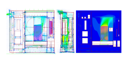
Figure 5. [Thermal design of composite cold plates by topology optimization]
Topology optimization leverages computational algorithms to design fluid pathways tailored for specific thermal and flow objectives. Rather than adhering to geometric simplicity, this method generates non-intuitive, high performance channel architectures that are often only manufacturable using additive manufacturing (AM) or advanced machining.
- Enhanced Heat Transfer Efficiency
Custom optimized channel paths maximize contact area and target high flux zones, substantially increasing heat removal. The result is more effective and faster cooling compared to traditional layouts.
- Increased Flow Rate, Lower Pressure Drop
By minimizing sharp turns and optimizing fluid velocity profiles, topology-optimized channels reduce flow resistance. This enables higher coolant throughput at a lower pumping power, improving both cooling efficiency and system energy consumption.
- Uniform Cooling Across the Component
Unlike uniform channel designs, topology-optimized layouts adapt coolant flow distribution to match localized heat generation. This ensures temperature uniformity, eliminates hotspots, and maximizes thermal utilization across the cold plate footprint.
Manufacturing Freedom with metal 3D printing
While topology optimization can significantly enhance thermal and hydraulic efficiency, unlocking its full potential requires manufacturing techniques that exceed the limits of conventional fabrication. Traditional machining struggles with the complex internal geometries produced by topology-optimized designs. That’s why metal additive manufacturing (AM)—particularly Laser Powder Bed Fusion (LPBF) and Electron Beam Melting (EBM)—has become essential for producing advanced cold plate cooling systems. These technologies offer the geometric flexibility and precision control needed to realize intricate fluid channels, internal manifolds, and organic shapes with high repeatability. By enabling performance-driven design unconstrained by traditional manufacturing, AM makes it possible to build next-generation cold plates tailored for extreme thermal demands.
- Complex Internal Channel Fabrication
Topology optimized channels often feature non-planar, spatially varying cross-sections, branched micro-pathways, and gradual transitions that are not feasible with CNC machining or traditional brazing. Metal AM enables:
- Internal bifurcations, multi scale channels, and embedded manifolds.
- Monolithic construction, eliminating interface resistances and leak prone joints.
- Precise control over local wall thickness and porosity, supporting tailored thermal behavior.
This unlocks design for performance, where the geometry is driven by physics and not by fabrication constraints.
- Performance to Weight and Volume Advantages
With Additive Manufacturing, designers can:
- Integrate lattice supports or conformal cooling passages into thermally critical regions
- Maintain structural integrity while reducing weight and volume, essential for aerospace and high density electronics
- Consolidate multiple cooling components (e.g., channels, manifolds, mountings) into a single part, improving reliability and reducing assembly time
- Improved Cooling Efficiency via Design Adaptation
By coupling topology optimization algorithms with AM compatible constraints (e.g., overhang angles, powder removal ports), cold plates can be fabricated that:
- Match coolant delivery to heat flux gradients
- Reduce thermal resistance and pumping power simultaneously
- Withstand cyclic thermal and pressure loading through tailored material deposition and post-processing treatments (e.g., HIP for density enhancement)
- Validation and Standards Alignment
3D printed cold plates can undergo the same rigorous reliability testing (e.g., ASTM B117 for corrosion, IEC 62368-1 for pressure) as traditionally fabricated units. Additionally, in-situ monitoring and non-destructive evaluation (e.g., CT scanning) ensure build quality and defect detection before deployment.

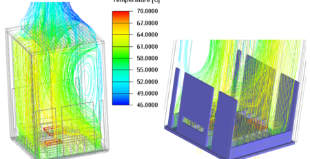
Figure 6. [Liquid-cooled cold plate for automotive power electronics]
Key Thermal Considerations for Liquid Cold Plate Design
Establishing component level Thermal Mapping
The first design step is developing a thermal map. This acts as a blueprint for the entire system and It identifies the hot spots and heat distribution across the device. This step includes:
- The size, location, and power dissipation of each component
- Allowable surface temperatures (global or per component)
- Coolant properties: type, flow rate, and inlet temperature
- Total available pressure drop across the cold plate
- Compute local heat fluxes including thermal spreading effects within the base plate.
A well constructed thermal map is the strategic foundation that informs channel layout, flow balancing, and heat exchanger geometry.
Critical Inputs for evaluating Thermal Performance:
Developing a custom cold plate design starts with understanding key thermal and hydraulic inputs. These core factors directly influence the architecture, flow path strategies, and the overall design complexity of the cold plate. By aligning performance requirements with physical constraints, engineers can make informed decisions early in the design process. The matrix below summarizes the most critical design drivers and how they affect system complexity, serving as a practical guide for optimizing both performance and manufacturability.


Leave a Reply