
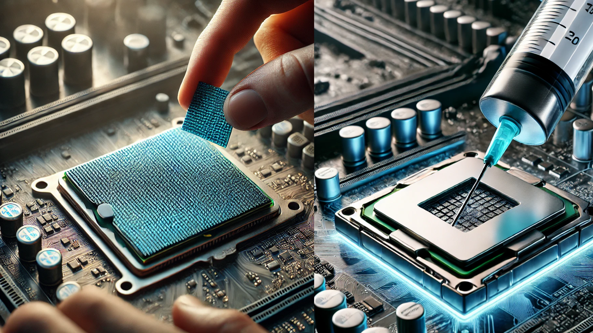
Thermal Interface Materials (TIMs): The Backbone of Efficient Thermal Management
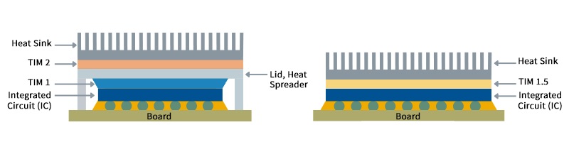 Figure 1. [Identifying TIM1, TIM1.5, and TIM2]
The integration of Thermal Interface Materials (TIMs) into High-Performance Computing (HPC) systems offers numerous substantial benefits, including enhanced heat transfer and improved system performance by reducing thermal throttling. Here are additional advantages:
- Minimized Risk of Component Failure: Overheating is a significant cause of component failure. By efficiently managing component temperatures, TIMs substantially reduce the risk of failure, thereby enhancing the reliability and longevity of HPC systems.
- Increased System Uptime: Consistent and reliable operation is critical in HPC environments. TIMs play a crucial role in preventing temperature-related disruptions, contributing to greater system uptime. This reduces the likelihood of system crashes and downtime, which could otherwise lead to significant operational interruptions.
By addressing thermal, electrical, and structural requirements, TIMs not only improve heat transfer efficiency but also ensure the safety and reliability of sensitive components. This comprehensive guide explores the diverse types of TIMs, their applications, and the critical role they play in modern thermal management strategies, ensuring they are indispensable in managing heat in electronic devices despite their inherent challenges.
Selection of Thermal Interface Materials for High-Performance Data Centers
High-performance data centers necessitate superior thermal management to maintain optimal operation temperatures and ensure system reliability. Thermal Interface Materials (TIMs) are crucial for achieving these objectives due to their ability to efficiently conduct heat away from critical components. Here’s an overview of the types of TIMs suited for such environments:
Phase Change Materials (PCMs): PCMs provide a dynamic cooling solution, absorbing heat by transitioning from a solid to a liquid state, making them highly effective for data centers, AI processors, and cloud computing. Their ability to handle transient thermal spikes makes them indispensable in high-power applications, such as servers, gaming rigs, and industrial automation systems. PCMs ensure sustained efficiency, reducing thermal resistance and improving long-term performance reliability.
Thermal Greases: Commonly used across various electronic applications, thermal greases are favored for their ability to fill microscopic gaps between components, enhancing contact and reducing thermal resistance. Their high thermal conductivity is crucial for maintaining the performance of CPUs, GPUs, and other heat-generating components.
Thermal Adhesives: Thermal adhesives not only provide strong mechanical bonds between components but also offer high thermal conductivity. They are particularly suitable for applications where a permanent bond is required, such as in the attachment of heat sinks directly to components.
Graphite-Based TIMs: Graphite-based TIMs offer excellent thermal conductivity and are often selected for applications where low thermal resistance is critical. Their unique anisotropic properties allow for superior heat spreading capabilities, making them effective as heat spreaders in high-performance systems.
Silicone-Based/Thermal Pads TIMs: These TIMs strike a balance between good thermal conductivity and electrical insulation. Their versatility makes them suitable for a broad range of applications within data centers, particularly where electrical isolation is a concern.
Key Considerations for TIM Selection in High-Performance Data Centers
When choosing a TIM for a high-performance data center, several factors must be carefully considered to ensure optimal thermal management and system integrity:
- Thermal Conductivity: Select a TIM with high thermal conductivity to minimize thermal resistance and enhance heat transfer from hot components to cooling solutions.
- Electrical Insulation: Ensure the TIM provides adequate electrical insulation to prevent potential shorts and other electrical issues, particularly important in densely packed environments.
- Compatibility: The chosen TIM should be chemically and physically compatible with the components it contacts, including CPUs, GPUs, and other critical hardware, to prevent material degradation or adverse chemical reactions.
- Temperature Range: The TIM should perform consistently across a broad temperature range, typically from -40°C to 125°C or higher, to accommodate varying operational conditions.
- Thermal Cycling Durability: It is crucial that the TIM withstands the stresses of repeated thermal cycling, a common occurrence in data centers, without degrading in effectiveness.
By addressing these key considerations, data center operators can select a TIM that not only meets the specific needs of their thermal management system but also contributes to the overall efficiency, reliability, and longevity of the data center operations.
Understanding types of TIMs:
Choosing the right Thermal Interface Material (TIM) depends on factors like thermal conductivity, durability, and application needs. Among the most efficient solutions, metal-based TIMs stand out for their superior thermal conductivity. These materials, including solder TIMs (STIMs) and liquid metal TIMs, provide high heat dissipation efficiency, making them ideal for AI processors, gaming GPUs, and high-performance computing systems.
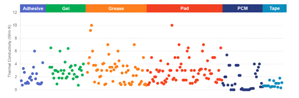 Figure 2. [Thermal Conductivity for Available TIMs in the Market]
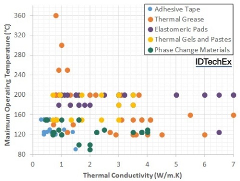
Figure 3. Maximum Operating Temperature for Commercially Available TIMs
Thermal grease
Thermal grease, or thermal paste, remains a top choice for electronics cooling, particularly in gaming PCs, high-performance laptops, and AI accelerators. This highly conductive TIM fills microscopic air gaps between the processor and heat sink, improving heat transfer efficiency. Compared to air, which acts as an insulator, thermal grease ensures optimal thermal performance, reducing CPU and GPU overheating risks.
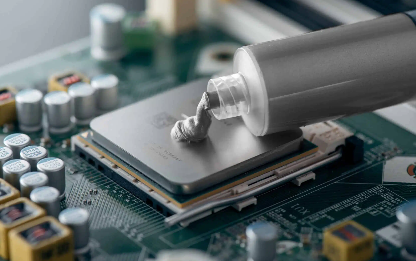
Figure 4. [Thermal Grease]
What Makes Thermal Grease Effective?
Thermal grease is a blend of silicone or hydrocarbon oils combined with thermally conductive particles like aluminum oxide, zinc oxide, or boron nitride. These fillers significantly boost the material’s thermal conductivity, enabling it to transfer heat more effectively between components such as heat sinks and processors. For applications where silicone is unsuitable, silicone-free alternatives are available to meet the needs of industries that prioritize material compatibility or surface adhesion.
Applications and Key Benefits
Thermal grease stands out as one of the most versatile and accessible TIMs available today. Its widespread use among DIY enthusiasts, prototype developers, and small-scale manufacturers stems from its flexibility and ease of application. Unlike pre-cut pads, which can be costly to customize, thermal grease can be applied using stencils or templates, making it a cost-effective choice for achieving uniform coverage.
The pseudo-fluid nature of thermal grease makes it especially suitable for flat, smooth surfaces. When pressure is applied, the grease spreads into a thin, uniform layer, reducing thermal resistance. This unique ability to conform to microscopic irregularities ensures efficient heat transfer across tight interfaces, making it ideal for applications that demand precision.
Challenges and Considerations
While thermal grease has numerous advantages, it is not without challenges:
- Messy Application:
Applying thermal grease requires precision and care due to its viscous nature. Improper application can result in uneven coverage, and larger quantities often lead to messiness, particularly in industrial or large-scale applications.
- Pump-Out Phenomenon:
A common issue with thermal grease is “pump-out,” where the material migrates out of the interface over time due to temperature fluctuations or vibration. This can leave the interface dry, reducing thermal performance and potentially contaminating nearby components. Applications that involve frequent on-and-off cycles are particularly susceptible to this issue, necessitating regular maintenance or reapplication.
Managing Thermal Grease Under Pressure
To achieve optimal performance, thermal grease requires mechanical clamping—typically with spring-loaded mounts—to ensure continuous contact between the surfaces it interfaces. When exposed to heat, the grease’s viscosity decreases, allowing it to flow and wet the surfaces more effectively. However, this softening reinforces the need for consistent pressure, as any loosening could reduce the thermal efficiency of the interface.
The Drawbacks: Mess and Reusability
One of the most frustrating aspects of thermal grease is how easily it spreads to unintended areas, including clothing, nearby components, and tools. Although small tubes and syringes help improve control during application, larger containers can exacerbate the mess, especially in high-volume industrial use.
Additionally, thermal grease is inherently non-reusable. Once compressed into a thin layer, it cannot be reclaimed or reapplied without introducing air pockets, which would undermine its effectiveness. Over time, the volatile components of the grease may outgas, leaving behind a dried residue that requires thorough cleaning before a fresh application.
Innovations in Thermal Grease
Despite being one of the oldest TIM technologies, thermal grease continues to evolve. New formulations are being developed to address its traditional drawbacks, such as pump-out and drying over extended use. These innovations cater to modern applications, particularly in microprocessor packaging, where high performance and long-term reliability are essential.
Gap Fillers:
For industrial electronics, power modules, and automotive systems, thermal gap fillers provide an effective cooling solution. Made from elastomeric sheets infused with highly conductive fillers, these materials bridge thermal gaps and enhance heat dissipation. Their ability to conform to irregular surfaces makes them ideal for power electronics, PCB assemblies, and high-density server cooling systems. One of the standout features of gap fillers is their versatility—they are available in a variety of configurations, making it easy to select the right material for a given application. Whether for standard device sizes or custom shapes, gap fillers provide a reliable solution for managing heat in diverse scenarios. A typical compression percentage for gap fillers is between 10% and 40% of their original thickness, with most recommendations falling around the 30% mark.
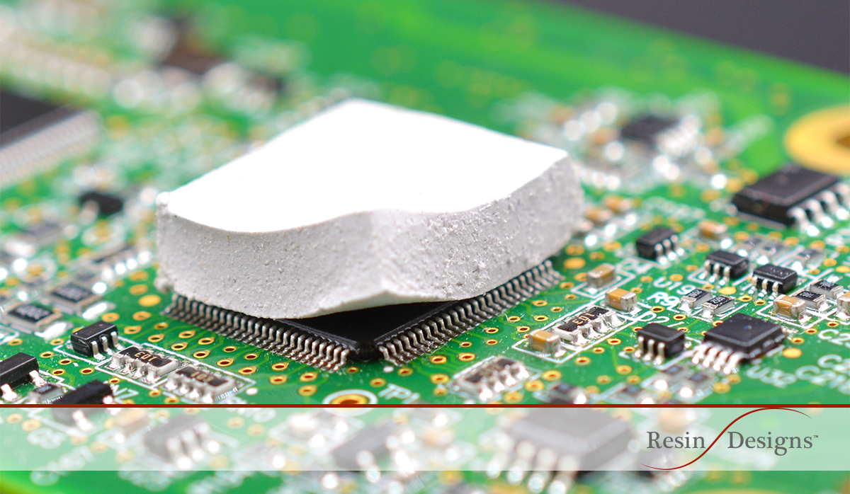
Figure 5. [Thermal Gap Filler ]
Material Diversity in Gap Fillers
Gap fillers are arguably one of the most versatile categories of TIMs, offering a broad range of options to suit specific needs. At their core, gap fillers combine an elastomeric base with thermal fillers, but this basic composition can be tailored in numerous ways:
Base Material Options: While silicone is the most common base material, silicone-free alternatives are available for applications sensitive to silicone emissions.
Thickness Variability: Gap fillers come in multiple thicknesses, allowing them to bridge small or large gaps as needed.
Surface Adhesion: They are available with tacky or adhesive surfaces on one or both sides to aid in secure placement during assembly.
Reinforcements and Carriers: Fiberglass reinforcements or carrier layers can be added to improve structural integrity and ease of handling.
Specialized Properties: Some gap fillers are designed to provide electrical insulation, while others can absorb electromagnetic interference (EMI).
This remarkable range of configurations makes gap fillers a popular and adaptable choice for thermal management across industries.
Addressing Tolerance Stack-Up and Complex Geometries
One of the key advantages of gap fillers is their ability to accommodate tolerance stack-ups and varying surface heights. Thanks to their elastomeric base, gap fillers are inherently compressible, which allows them to apply pressure proportionally to the surfaces they contact. This elasticity enables them to conform to uneven surfaces and varying heights across their entire area.
- Accommodating Multiple Devices: Gap fillers can connect multiple devices of different heights to a single heat sink, ensuring effective thermal contact across all components.
- Bridging Variances: They excel in applications where manufacturing tolerances create slight variances in component positioning or surface geometry.
This flexibility makes gap fillers an ideal choice for complex assemblies where precise alignment between components and heat sinks is not always feasible.
Reusability and Limitations
Gap fillers also offer some degree of reusability, a feature not commonly found in many TIMs. Their elastomeric nature allows them to regain their original shape after compression, provided they are not pushed beyond their elastic limits. However, there are important considerations when reusing gap fillers:
- Plastic Deformation: Over-compressing the material can cause permanent deformation, reducing its effectiveness in subsequent applications.
- Adhesive Challenges: If the gap filler has an adhesive side, reusability becomes limited as the adhesive may degrade or pick up contaminants during removal.
- Clean Environment Required: Adhesive or tacky surfaces can easily attract particles like dust, compromising the material’s ability to maintain consistent thermal contact upon reinstallation.
- For optimal reusability, careful handling and a clean, controlled environment are essential during deinstallation and reinstallation processes.
Impact of Thickness on Performance
The difference between managing gaps measured in millimeters versus microns is critical to the thermal performance of the material:
- Thicker Gap Fillers:
Thicker gap fillers are generally more prone to instability under conditions like vibration or thermal cycling. This is because thicker layers of material can shift or displace more easily, potentially compromising their ability to maintain consistent thermal contact. Over time, this displacement can lead to performance degradation.
- Thinner Gap Fillers:
Using a gap-filling material for applications requiring extremely thin layers, such as a traditional thermal interface (measured in microns), may result in challenges like uneven distribution or difficulty in achieving a consistent, uniform layer. Thin films of gap fillers may have higher thermal resistance at the interface, reducing heat transfer efficiency and increasing the potential for hotspots.
Matching Materials to Dimensions
Selecting a gap filler with the right thickness and thermal conductivity is essential for ensuring stability and optimal heat transfer. For larger gaps, elastomeric sheets with high compressibility and appropriate thermal conductivity are preferred to minimize displacement risks while still providing effective heat management. For thinner applications, alternative TIMs such as thermal greases or pads might be better suited, as they can achieve a more uniform, low-resistance interface.
Thermal Pads and Films:
Thermal pads and films are essential components in advanced thermal management, providing a highly efficient interface for heat transfer between components. These versatile TIMs help prevent hotspots, ensuring stable operation in consumer electronics, industrial machinery, and high-performance computing (HPC) systems. Their customizability makes them ideal for smartphones, gaming consoles, and power electronics, offering a low-maintenance, high-efficiency cooling solution.
Thermal Pads
Thermal pads are composed of silicone-based materials with higher durometer values compared to gap fillers, making them sturdier and better suited for consistent thermal performance. These pads are often infused with thermally conductive fillers, such as aluminum oxide or boron nitride, to enhance heat transfer. Reinforcement with materials like fiberglass further improves their durability and tear resistance, making them a robust alternative to traditional thermal hardware. Their ease of handling and installation has made them a go-to solution for applications requiring reliable thermal conductivity and mechanical stability.
![]()
Figure 6. [ Graphene Thermal Pad ]
Thermal Films
Thermal films, typically made from polyimide (often branded as Kapton), are ultra-thin and provide excellent electrical insulation along with thermal conductivity. These materials excel in applications requiring lightweight, compact solutions, particularly in high-performance electronics where space is at a premium. Some thermal films are made from materials like graphite, offering unique properties that address specialized thermal management challenges.
Graphite Pads and Films
Graphite pads and films stand apart from other thermal interface materials due to their unique structure and properties. Made from stacked graphene sheets, these materials allow heat and electricity to travel effortlessly along their planes, making them exceptional at spreading heat laterally. However, because the bonds between the graphene layers are weak, graphite pads are relatively brittle and prone to damage. Additionally, unlike many thermal pads and films, graphite is not electrically insulating, as electrons can flow through its structure.
Graphite materials are a practical alternative to thermal greases or pastes in applications where high temperatures—beyond 200°C—are encountered. Thanks to their high-temperature resistance, they can be used effectively in harsh conditions, and in extreme scenarios, placing graphite films in a vacuum prevents oxidation of the carbon. Furthermore, graphite films can provide EMI shielding up to GHz ranges, making them highly valuable for applications requiring both thermal management and electromagnetic interference protection.
Elastomeric Pads
Elastomeric pads are a natural progression from greases, offering a more solid and easy-to-handle alternative. These pads are made from polymerized silicone rubbers, typically with a thickness of 0.25 mm, and are reinforced with woven fiberglass to enhance their structural integrity. Much like greases, they contain thermally conductive fillers to optimize performance. Elastomeric pads are often pre-cut into specific shapes, simplifying assembly for common applications like TO transistor packages. However, to ensure proper contact and thermal transfer, these pads require high pressures—around 700 kPa—to perform effectively.
Electrical Isolation and Material Flexibility
One of the standout features of many thermal pads and films is their ability to provide electrical insulation. Electrically insulating materials like polyimide-based films are becoming increasingly popular due to their lightweight and thin design, particularly in consumer electronics where compactness is critical. Conversely, non-insulating options like graphite provide unparalleled thermal spreading capabilities, making them suitable for high-power applications where electrical isolation is not a requirement.
Key Benefits of Thermal Pads and Films
Versatility: Available in various materials, sizes, and configurations to suit specific thermal and mechanical requirements.
Durability: Reinforced with fiberglass or other materials to resist tearing and maintain performance over time.
Customizability: Offered in standard or customized shapes for precise fits in diverse applications.
Electrical Properties: Options for both electrically insulating and non-insulating materials to address a wide range of use cases.
High-Temperature Performance: Graphite-based films excel in high-temperature environments, while silicone-based materials provide reliable performance under moderate conditions.
Thermal tapes:
Thermal tapes are an innovative interface material, has simplified the attachment of heat sinks to various components, streamlining the assembly process by eliminating the need for external clamps. These tapes are imbued with pressure-sensitive adhesives (PSAs) that adhere to surfaces through mere contact and a small amount of pressure. Commonly supported by materials such as polyimide film, fiberglass mat, or aluminum foil, thermal tapes are essential in applications ranging from everyday items like bandages to complex electronic assemblies.
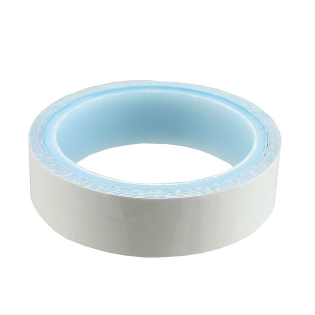
Figure 7. [Thermal Tape]
Key Characteristics and Applications
The use of thermal tapes is primarily driven by their adhesive properties rather than their thermal performance, which typically ranges from 1 to 4 K·cm²/W. This performance is highly dependent on the quality of the contact surface. One limitation, however, is their restricted compliance, making them less suited for certain types of electronic packaging, such as over-molded Ball Grid Array (BGA) packages with concave surfaces. Thermal tapes are distinguished from regular double-sided tapes by their specialized formulation, which includes high thermal conductivity fillers and polymers. This composition ensures an effective mechanical bond between surfaces, a critical feature in thermal management.
Challenges in Handling and Reusability
Handling thermal tapes can be challenging, especially the baseless types that are prone to premature sticking. This difficulty is mitigated by using tapes with a carrier film, which aids in application without compromising the tape’s integrity. Despite these advantages, thermal tapes are typically not reusable once applied, as removing them can damage their structure and reduce their effectiveness. If rework is required, the tape must be carefully heated or treated with solvents to dissolve the adhesive, necessitating a clean application surface for any subsequent uses.
Considerations for Heavy Applications
While thermal tapes are invaluable for mounting smaller devices and heat sinks, their use in heavier applications should be carefully considered. The mechanical strength of the tape may not withstand the weight and stresses associated with larger heat sinks or environments subject to high vibration or shock. In such cases, alternative thermal interface materials should be considered. Overall, thermal tapes offer a versatile and effective solution for heat management in electronic assemblies, particularly where ease of use and space-saving are priorities. However, their limitations in terms of mechanical strength and reusability require careful consideration to ensure they meet the specific needs of each application.
Phase change materials (PCMs)
PCMs are an innovative class of thermal interface materials that combine the high thermal performance of greases with the ease of handling typically associated with elastomeric pads. Initially developed in the 1980s, PCMs gained significant traction during the 1990s, particularly in assembly lines where they could be pre-applied to heat sinks. This approach allowed manufacturers to streamline final assembly processes without dealing with the messiness of grease.

Figure 8. [PCM]
What Are Phase Change Materials?
At their core, phase change materials are wax-based substances that melt within a temperature range of 50°C to 80°C. Classified as low-temperature thermoplastic adhesives, PCMs exhibit excellent heat conduction properties both above and below their melting point. However, once they transition to a viscous liquid state, they lose adhesive strength and require mechanical support, such as clamps, to maintain proper interface pressure—typically around 300 kPa. PCMs are available in various configurations, including supported and unsupported versions, often enhanced with thermally conductive fillers to improve their heat transfer capabilities. These fillers, combined with their phase-changing properties, enable PCMs to achieve thermal resistance levels comparable to grease, generally ranging from 0.3 to 0.7 K·cm²/W.
The Science Behind Phase Change Materials
The phase-changing property of PCMs allows them to transition from a solid to a viscous liquid as they absorb heat. This phase transition occurs at a specific temperature (typically 55°C to 65°C), during which the material maintains a consistent temperature while absorbing the heat required to complete the melting process (latent heat of fusion). This characteristic enables PCMs to provide superior temperature control during operation. Once melted, PCMs flow into microscopic voids and surface imperfections, creating a uniform thermal interface and eliminating air pockets. This ability to conform to even the roughest surfaces ensures consistently low thermal resistance between components, enhancing heat transfer efficiency.
Advantages of PCMs
Ease of Handling and Application:
At room temperature, PCMs are solid, making them much easier to handle, process, and apply compared to traditional greases. Their solid-state form allows for pre-application to heat sinks, simplifying the assembly process for manufacturers.
Improved Conformability:
Once melted, PCMs infiltrate every nook and cranny of the surfaces they interface, effectively filling gaps that other TIMs might struggle to address. This makes them particularly effective on surfaces with slight imperfections.
Cleaner Maintenance:
Unlike greases, PCMs revert to a solid form upon cooling, making them less messy to clean during maintenance or rework. Cleaning agents like isopropyl alcohol are often sufficient to remove residual material.
Thermal Performance Close to Grease:
While offering easier handling and less mess, PCMs achieve thermal conductivity levels similar to that of greases, making them an attractive alternative for applications requiring both performance and convenience.
Challenges of Phase Change Materials
Despite their many advantages, PCMs are not without limitations:
Reworkability:
Although PCMs are not classified as adhesives, their residual adhesion during rework can pose risks to expensive components, especially in delicate systems. This has prompted some manufacturers to revert to grease for high-performance microprocessors.
Sensitivity to Misapplication:
PCMs require precise installation and proper pressure during operation to achieve optimal performance. Spring-loaded mounting mechanisms are often necessary to compress the material as it thins out upon melting, ensuring minimal interface resistance.
Cost Considerations:
PCMs tend to be more expensive than traditional greases and pads. This higher cost, combined with their limited reworkability, makes them less appealing for some applications.
Configurations and Applications
PCMs are available in various forms, including bulk rolls, pre-cut sheets, dispensable liquids, and even stick formats for rub-on applications. Many PCM products are integrated with thermal films or aluminum foils to improve structural integrity and make handling easier. These configurations offer flexibility in addressing specific thermal management needs.
For example:
Pre-Cut Sheets or Shapes: Ideal for standard device packages, ensuring consistent application.
Dispensable Fluids: Harden to a solid-state after application, suitable for non-standard shapes or complex geometries.
Thermal Pads: Combine PCM with supporting materials to enhance durability and insulation properties.
Performance in High-Temperature Applications
PCMs excel in bridging thermal gaps on surfaces that experience frequent thermal cycling. However, they are not reusable; once applied and melted, their original state cannot be restored. Nevertheless, their phase-changing behavior makes them an ideal choice for applications that benefit from their ability to conform to irregularities and reduce thermal resistance consistently.
Thermal Epoxy
For applications requiring both structural integrity and high thermal conductivity, thermal epoxy is the ideal heat dissipation solution. Infused with ceramic particles and metal fillers, this high-performance TIM not only ensures efficient heat transfer but also provides strong mechanical adhesion. Perfect for power electronics, aerospace components, and industrial machinery, thermal epoxy is a long-term, reliable alternative to thermal grease and pads.
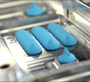
Figure 9. [Thermal Epoxy]
What Makes Thermal Epoxy Unique?
Thermal epoxy serves a dual purpose: it functions both as a thermal interface material and as a mechanical bonding agent. By curing into a rigid structure, it creates a strong adhesive bond between the surfaces it connects, enabling it to securely join components such as heat sinks to devices. This ability to serve as both a TIM and a mounting solution can reduce the need for additional hardware, simplifying designs and improving the overall efficiency of the assembly process.
Thermal epoxies are available in two primary forms:
One-Part Resins: Pre-mixed and ready to apply, these resins cure when exposed to heat or air, offering convenience in straightforward applications.
Two-Part Resins: These require mixing before application, offering greater flexibility in adjusting cure times and adhesion properties based on the specific needs of the application.
The type of epoxy used depends on the materials being bonded and the thermal performance requirements of the device.
Advantages of Thermal Epoxy
Strong Mechanical Bonding:
Thermal epoxy provides a level of mechanical strength unmatched by other TIMs. This makes it an ideal solution for applications requiring a reliable, long-term bond, such as epoxy-bonded heat sinks in electronics.
Thermal Efficiency:
The inclusion of thermally conductive fillers allows epoxy to effectively transfer heat, helping to maintain temperature control in high-performance devices.
Hardware Reduction:
Since thermal epoxy doubles as an adhesive, it can reduce or eliminate the need for mounting brackets, clamps, or other hardware, simplifying designs and lowering production costs.
Versatility:
With various formulations available, thermal epoxy can be tailored to different materials and application environments.
Limitations and Considerations
While thermal epoxy offers several advantages, there are important considerations to keep in mind:
Non-Reusability:
Once cured, thermal epoxy cannot be removed or reused. The polymeric bonds formed during curing are incredibly strong and resistant to mechanical or chemical breakdown. This makes rework or maintenance on epoxied components challenging, especially in sensitive devices like circuit boards.
Removal Challenges:
Removing cured thermal epoxy often requires aggressive methods, such as sawing or milling, which can risk damaging surrounding components. For devices that may require frequent maintenance or updates, thermal epoxy may not be the ideal choice.
Shipping Limitations:
Uncured thermal epoxies often contain volatile chemicals, which can complicate shipping. Air freight companies may impose restrictions due to safety concerns, meaning ground shipping is often required. This factor may impact logistics and lead times, especially for time-sensitive projects.
Precision in Application:
Thermal epoxy must be applied with care. Once curing begins, adjustments are difficult, so precise placement and alignment are essential. Factors like temperature, humidity, and the epoxy’s cure time can affect its usability, making preparation critical.
Best Practices for Using Thermal Epoxy
Plan Ahead: Since cured epoxy cannot be reworked, ensure proper alignment and positioning before application. Familiarize yourself with the specific cure time and environmental conditions required for the epoxy you are using.
Use Appropriate Solvents for Cleanup: Uncured epoxy is easier to clean than cured resin. Solvents like isopropyl alcohol can help remove residue before curing begins.
Understand Shipping Restrictions: If you’re ordering uncured epoxy, verify shipping regulations and plan accordingly to avoid unexpected delays.
Choosing the Best Thermal Interface Material: A Focus on Material Compatibility
When it comes to selecting the optimal thermal interface material (TIM) for modern electronic applications, performance metrics such as thermal conductivity and resistance often dominate the decision-making process. However, the issue of material compatibility should not be overlooked, as it can be a critical factor in ensuring the longevity and reliability of electronic components.
Gels:
These gels, available in both liquid formable and curable formulations, enhance their applicability across diverse scenarios. Unlike traditional pads with pressure-sensitive adhesive, these thermal interface materials are dispensed directly as pre-cured, single-component compounds. This application method ensures that they are not only easy to apply but also offer the flexibility to be reworked, making them ideal for iterative development processes.
Gap filler gels excel in providing extensive compression ranges with minimal force required, ensuring an exceptionally well-wetted joint while exerting little stress on the joint surfaces. They marry the conformability of curable compounds with an excellent shelf life, streamlining both the production and maintenance processes.
Additionally, these gels are tailored for low component stress and high rework simplicity, which enhances process flexibility and in-application stability. Their efficient thermal conductivity makes them highly effective across various settings, particularly in industrial and automotive applications where reliable heat dissipation is crucial. This combination of features makes these thermal interface gels a versatile and essential tool in advanced thermal management strategies.
High-performance Thermal Interface Materials (TIMs) play a vital role in heat management for high-power electronics and AI-driven computing. As devices become smaller yet more powerful, efficient thermal dissipation is necessary to prevent overheating and system failures. In data centers, AI processors, and HPC environments, selecting the right TIM solution ensures maximum cooling efficiency, energy savings, and long-term device reliability.
This is essential to ensure the reliability, efficiency, and longevity of the equipment. TIMs are crucial in enhancing the thermal management strategy by effectively reducing thermal resistance and facilitating efficient heat transfer from high-heat generating components such as CPUs, GPUs, and power units to heat sinks or cooling modules. Below are some TIMs for use in high-performance data centers, each based on their performance characteristics and suitability for demanding applications:
Metal TIMs
Solder TIMs (STIMs): Solder TIMs are primarily used as TIM1 materials, placed between the top of a bare flip chip die and the flip chip lid. They are favored for their excellent thermal conductivity and strong mechanical bond, which not only ensures superior heat transfer but also enhances the structural integrity of the semiconductor package.
STIM are specialized materials designed for high-performance thermal management between the integrated heat spreader (IHS) and the processor die. STIMs employ solder to create a strong mechanical bond and superior thermal connectivity between interfacing surfaces. This integration not only secures the components mechanically but also ensures minimal thermal resistance due to the formation of efficient intermetallic connections.
Distinctive Advantages of STIMs
The primary advantage of using STIMs lies in their high bulk thermal conductivity and the low interfacial thermal resistance achieved post-soldering. This makes them exceptionally suitable for applications (TIM1) where optimal heat dissipation is critical. For instance, in high-power computing systems, the effective heat transfer provided by STIMs is crucial for maintaining system stability and performance.
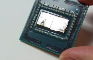
Figure 10. [AMD Ryzen 7 with Solder TIM]
Application Specifics and Considerations
Utilizing STIMs, however, comes with its set of requirements and challenges:
Metallization Needs: Both surfaces to be joined must be appropriately metallized. This preparation is necessary for the solder to properly adhere and form effective intermetallic compounds.
Reflow Process: The solder TIM must undergo a reflow process, which can complicate manufacturing stages, especially post-circuit board assembly. Additional reflow can introduce reliability issues due to potential failures from thermal stresses elsewhere on the board.
Void Formation: Solder reflow inherently leads to some degree of voiding within the joint. These voids can impair thermal transfer and are often exacerbated by multiple reflow cycles.
Compressible TIMs:
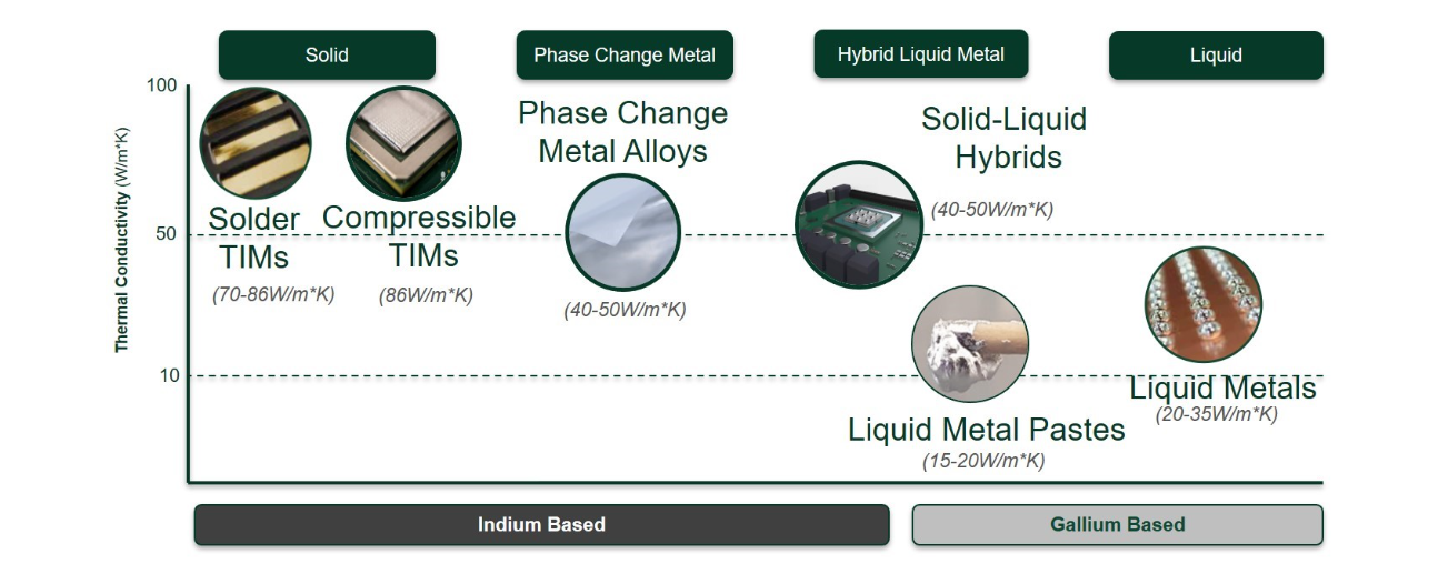
These are typically used as TIM2 materials and are ideal for applications requiring minimal mechanical stress on the components, such as between the heat spreader and the secondary heat sink. Compressible TIMs offer flexibility and good thermal performance, making them suitable for uneven surfaces where a strong mechanical bond is less critical. When using a compressible metal TIM, the performance will improve over time as the material requires time to achieve the plastic deformation required to fill all air gaps. This can be accomplished with a 12-hour pre-load of pressure onto the TIM. The patterning of TIMs dramatically improves the compressibility of the material. For example, a flat foil of pure indium might require 100 PSI to get compression. By patterning the foil, you can reduce the required pressure by more than 50%.
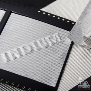
Figure 11. [Compressible Metal TIMs]
Liquid Metal TIMs:
Increasingly popular in AI accelerators, gaming laptops and consoles, liquid metal TIMs are noted for their exceptional thermal conductivity and ability to conform to surface irregularities, filling micro gaps and cracks efficiently. These TIMs are versatile enough to be used as TIM0, TIM1, or TIM2 materials. They mainly consist of gallium alloys. Gallium is not compatible with aluminum, but anodizing the aluminum can overcome the issue. Two significant temperatures associated with the liquid metal TIM is Liquidus and solidus. liquidus is the lowest temperature at which an alloy is completely liquid; solidus is the highest temperature at which an alloy is completely solid. These temperatures are crucial because they determine the material’s phase behavior, which directly affects its thermal performance, reliability, and application feasibility. Their fluid nature allows for very thin bond lines, significantly reducing thermal resistance and improving heat dissipation.
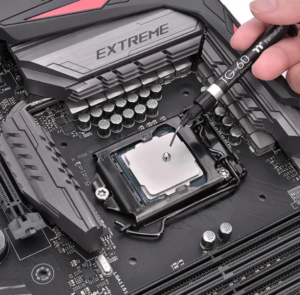
Figure 12. [Liquid Metal TIMs]
Metal Phase Change Material (PCM)
Thermal Interface Materials offer a unique hybrid approach to thermal management, combining high thermal conductivity with adaptive phase change properties. These materials effectively absorb and dissipate heat, making them ideal for high-power processors, AI-driven computing, and next-gen semiconductors. By transitioning between solid and liquid states, they provide dynamic thermal response, ensuring optimal cooling efficiency in high-performance computing (HPC) and industrial applications.
Metal PCM TIMs utilize low melting point alloys that can be preformed and easily applied using pick and place machines or robotic arms. These preforms offer tight tolerances, allowing for precise control over the volume of TIM used, which is a significant improvement over the application variability associated with liquid metal TIMs.
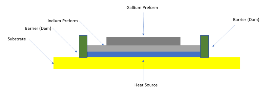
Figure 13. [ High Performance PCM TIMs]
Operational Mechanism and Benefits
Upon reaching operational temperatures, typically in the range of 70–100ºC, the alloy melts, transitioning to a liquid state that conforms perfectly to the micro surfaces of both the heat source and the heat sink. This property drastically reduces thermal resistance during operation. When the device is turned off and temperatures drop, the alloy solidifies, returning to its original form without degradation. This cycle can repeat with each use of the device, maintaining effective thermal management throughout the device’s lifecycle.
Compared to conventional TIMs, Metal TIMs offer several compelling advantages:
Higher Thermal Conductivity: For example, Indium-based solders used in STIMs can exhibit thermal conductivities as high as 87 W/m.K, significantly outperforming greases with typical conductivities of 3-12 W/m.K.
Stability and Durability: Unlike thermal greases that can migrate and pump out under thermal cycling, leading to increased thermal resistance over time, metal TIMs remain stable and do not degrade in performance. Their inherent malleability helps to maintain, and even improve, the thermal interface over time.
No Bake-out: STIMs do not suffer from the bake-out phenomenon, where the material dries out and loses effectiveness.
Clean and Precise Application: Metal TIMs can be applied in a controlled manner, often pre-packaged in forms suitable for automated assembly processes.
Challenges
- Metal TIMs are inherently electrically conductive. In scenarios where electrical isolation is necessary, such as in applications involving sensitive electronics, metal-based TIMs may not be appropriate. For instance, if there’s a need to prevent electrical shorts between the die and the heatsink, alternative TIMs that offer both thermal conductivity and electrical isolation would be required.
- Materials will tend to expand/contract during melting or solidification. Most metals will contract during solidification. Typically, this is less than a 1% volume change. The volume change can result in some mobility of the liquid. With the repeated phase change of a metal, you can see dewetting due to oxidation. This could result in voids. If the TIM is under significant pressure, the liquid can also squeeze out resulting in a possible electrical short of adjacent circuitry
- Metal-based TIMs with enhanced properties can be prohibitively expensive, increasing the overall cost of the electronic device.
- The need for specialized application techniques, such as precise deposition or the ability to handle phase changes without compromising system integrity, adds another layer of complexity. Furthermore, the market adaptation of these advanced materials can be slow, as industries weigh the benefits against the increased costs and integration challenges.
Typical thermal conductivity for metal TIMs is in the range of 15–86W/m*K. Figure 2 shows different types of metal TIMs and their typical thermal conductivity.
Carbon-Based TIMs
Carbon-based TIMs, including graphene, diamond, and carbon nanotubes (CNTs), offer exceptional thermal conductivity, often exceeding 1000 W/m·K, making them ideal for next-generation electronics. Used in AI accelerators, HPC processors, and high-frequency RF applications, these materials deliver unparalleled heat dissipation while maintaining mechanical stability. Their lightweight yet highly conductive properties make them a go-to solution for cutting-edge thermal management.
Graphite-Based TIMs:
Graphite is a staple in thermal management due to its excellent in-plane conductivity, making it ideal as a heat spreader to prevent hotspots. Its application ranges from smartphone batteries to display panels where thin graphite sheets are integrated to distribute heat evenly.
Figure 14. [GraphiteTIMs]
While graphite excels in-plane (x-y direction), its through-plane (z-direction) conductivity is comparatively lower, which can be a limitation when direct heat dissipation from the source is necessary. Products like NeoGraf’s HITHERM illustrate this application, offering around 800 W/m·K in-plane conductivity but only about 7 W/m·K through-plane. Enhancing through-plane conductivity remains a challenge, often requiring cost-intensive solutions like vertically aligned graphite, which can significantly increase the material cost.
Graphite pastes, using graphite as a thermal filler, represent another common application, typically offering thermal conductivities between 5 and 15 W/m·K. The cost of these pastes varies based on the graphite’s purity, the volume purchased, and other market factors.
Carbon Nanotubes (CNT) TIMs
Carbon Nanotube (CNT)-based Thermal Interface Materials (TIMs) offer exceptional thermal conductivity (up to 3000–6000 W/m·K for Single-Walled Carbon Nano Tubes (SWCNTs)) and minimal thermal resistance, outperforming traditional TIMs like greases and liquid metals. CNT TIMs can be in the form of vertically aligned CNT (VACNT) arrays, CNT-polymer composites, or CNT-metal hybrids, providing high durability, resistance to drying or pump-out, and stability under extreme temperatures (>500°C). Unlike liquid metals, they can be electrically insulating when mixed with polymers, making them safer for electronics. However, high manufacturing costs, interface resistance, and limited commercial availability remain challenges. Despite this, CNT TIMs are a promising next-gen solution for high-performance computing, aerospace, and power electronics, potentially replacing conventional TIMs as nanotechnology advances. Shinko is developing a CNT TIM which uniquely structured with high thermal conductivity and flexibility. The thermal conductivity stated is 50 W/mK with a TIM thickness of 50-150μm and a max temperature of 120 oC.
Diamond based TIMs
Diamond-based thermal interface materials (TIMs) offer exceptional thermal conductivity (up to 2000 W/m·K), far surpassing traditional TIMs like thermal greases and even liquid metals. Their high thermal stability (>1000°C), electrical insulation, and mechanical durability make them ideal for high-performance applications such as power electronics, aerospace, and high-performance computing (HPC). Diamond TIMs come in various forms, including diamond-filled polymer composites, diamond-metal hybrids, and chemical vapor deposition (CVD) diamond coatings, each offering unique advantages in thermal management. While high production costs and limited availability currently restrict their use to specialized industries, advancements in diamond synthesis and processing could make them a mainstream solution for next-generation thermal management in extreme-performance electronics.
Boron Nitride-Based TIMs
Boron Nitride (BN) is another high-performance material valued for its thermal conductivity, which can reach up to 600 W/m·K, and its electrical insulating properties. BN’s chemical and thermal stability make it safer and easier to handle compared to other high-performance materials, capable of withstanding temperatures above 1000°C without degradation. The form of BN used—whether hexagonal BN (h-BN) or cubic BN (c-BN)—can influence its effectiveness. Hexagonal BN is particularly valued for its layered structure that promotes high thermal conductivity and minimizes particle agglomeration, enhancing the material’s dispersion within composites.
However, the high cost of BN, typically ranging from $50/kg to $65/kg, restricts its use to applications where its cost can be justified by the performance benefits. Often, BN is used in combination with cheaper materials to optimize both performance and cost.
Common Compatibility Issues in Electronic Applications
One of the less considered, yet significant, compatibility concerns involves the interaction of TIMs with sensitive components such as humidity and gas sensors. For instance, silicone-based TIMs, while popular due to their excellent thermal and mechanical properties, can emit vapors that might damage these types of sensors. This can alter sensor readings or, worse, result in total sensor failure.
Furthermore, plastic optics and silicone-encapsulated LEDs present another challenge. These components may degrade or cloud over when exposed to certain organic vapors emitted by some organic-based TIMs. This degradation not only affects the performance of the LEDs but also compromises the optical clarity required in critical applications.
Evaluating TIM Options
Given these challenges, it is essential to evaluate TIM options not just on their thermal performance but also on their chemical properties:
Non-Silicone TIMs: These are preferable in applications where silicone vapors could cause issues, such as in optical systems or with certain sensors. Non-silicone TIMs avoid the risk of silicone migration, which can be particularly problematic in highly sensitive environments.
Phase Change Materials (PCMs): PCMs offer good thermal performance and minimal outgassing, making them suitable for use around sensitive components where vapor exposure is a concern.
Thermal Greases: While offering excellent thermal conductivity, greases can be prone to pump-out and may not be ideal for high-vibration environments or where minimal contamination is critical.
Graphite Pads: These provide good thermal conductivity and are stable at high temperatures. Being inorganic, they do not outgas and are an excellent choice for temperature-sensitive components.
Thermal Adhesives: These are used when a permanent bond is needed between the heat sink and the component. However, their irreversible nature should be considered in the design phase.
Conducting Compatibility Tests
To avoid unforeseen issues, it is wise to conduct thorough compatibility testing under actual operating conditions. This includes testing for chemical reactions, physical degradation, and thermal performance over the expected life span of the device.
How to Apply Thermal Interface Material: Techniques and Best Practices
Proper TIM application is key to maximizing heat dissipation and ensuring consistent thermal performance in CPUs, GPUs, and semiconductor components. Whether applied manually or via automation, the process must ensure uniform coverage, eliminate air gaps, and optimize thermal conductivity. High-precision application techniques, such as stencil printing or automated dispensing, improve thermal contact and enhance long-term device stability.
Understanding Different TIM Applications
- Automated Dispensing and Screen Printing: For mass production, manufacturers might automate the application of both non-curing and curing TIMs. Automation ensures precision and consistency, particularly important for products like CPUs and GPUs where the exact amount of TIM can significantly influence thermal performance. Non-curing products typically remain tacky and do not set, making them suitable for environments where rework may be necessary.
Curing products require a certain amount of time to set completely. If they dry too quickly, they might not be suitable for methods like stencil printing, as the quick-drying nature can clog screens or stencils.
- Manual Application: Manual application is common in custom or smaller scale operations. The technique varies based on the type of TIM but generally follows these principles:
Thermal Grease: Apply a small pea-sized dot in the center of the component and use a card or a specific tool to spread it evenly across the surface. The key is to create a thin layer that covers the entire surface without overflowing the edges.
Thermal Pads: Cut the pad to match the size of the heat spreader or component exactly. Place it gently, ensuring no air bubbles form underneath. This method is simpler and cleaner but less adaptable to uneven surfaces.
Gap Fillers: These are crucial for larger gaps and uneven surfaces. Apply the filler directly to one of the surfaces and then compress the components together to spread the material. It’s vital to expel all air during application, as trapped air can act as an insulator and lead to hotspots.
Special Considerations for Encapsulation Resin
If you are using encapsulation resin, typically in applications that require protection from environmental factors, you will likely need to cover more extensive areas, such as entire PCBs. The amount of resin used must balance adequately protecting the components without excessively adding to the volume or weight of the device. Proper technique involves:
- Even Application: Using tools like a spatula or a brush to spread the resin evenly.
- Curing Time: Allowing sufficient time for the resin to cure fully, according to the manufacturer’s specifications.
Tips for Effective TIM Application
Uniform Coverage: Always aim for a uniform coverage to eliminate hot spots and ensure optimal heat transfer. Use only the necessary amount of TIM; too much can be just as detrimental as too little.
Clean Surfaces: Before application, clean all surfaces thoroughly to remove dust, oil, and other contaminants. This improves the adhesion and effectiveness of the TIM.
Practice Makes Perfect: If you are new to applying TIM, especially in a manual setting, practice on old components to perfect your technique before applying it to critical hardware
Metal TIMs
Unlike more forgiving materials like silicone-based TIMs, metal TIMs can lead to issues such as “pump-out” or “squish-out” if not correctly applied. This necessitates precise control over the amount and placement of TIMs. For example, using an array of small dots rather than a single large blob can help ensure more uniform spread under compression and avoid dry spots.
For high-volume production environments, the deployment of liquid metal TIMs can be challenging. Conventional dispensing equipment designed for less reactive materials may require modifications to handle the unique properties of liquid metals effectively.
Guidelines for Selecting the Ideal Thermal Interface Material for Your Needs
Selecting the best TIM is essential for optimizing heat dissipation and reducing thermal resistance in high-performance computing, power electronics, and AI processors. The right thermal interface material enhances heat transfer efficiency, prevents thermal throttling, and extends device longevity. Key considerations include thermal conductivity, contact resistance, and material compatibility, ensuring maximum cooling performance in data centers, gaming PCs, and industrial electronics.
Here are key factors to consider when selecting a TIM:
- Thermal Conductivity/Resistance
Thermal conductivity is a primary indicator of a TIM’s ability to transfer heat. Materials with higher thermal conductivity reduce thermal resistance and improve heat transfer efficiency, making them preferable for applications where high thermal performance is critical.
- Ease of Application and Installation
The complexity and cost of applying TIMs can vary widely. For instance, thermal grease might require additional steps such as clamping and curing, which can increase both the cost and time of assembly. On the other hand, adhesive thermal tapes offer a simpler application process, which can be beneficial for less demanding thermal management scenarios. Assessing the application process is essential to optimize both cost and performance.
- Reliability and Longevity
Consistent performance over the lifespan of an electronic device is essential. Given that devices may be operational for decades, especially in sectors like avionics and telecommunications, the chosen TIM must withstand the rigors of time without degradation. The increasing miniaturization of electronic components and higher power densities makes the choice of a reliable TIM more critical than ever.
- Dielectric Strength & Electrical Insulation
In applications involving PCBs, LEDs, or power electronics, thermal interface materials (TIMs) specify dielectric strength and dielectric constant because these properties are critical in applications requiring both heat dissipation and electrical insulation. Dielectric strength, measured in kV/mm or V/mil, represents the maximum electric field a material can withstand before breaking down and becoming conductive. This is essential for preventing short circuits in electronic components, especially in high-voltage power electronics. A higher dielectric strength means the material can handle greater electrical stress before it allows current to pass through, which is critical in preventing short circuits, electrical overstress (EOS), and unintended leakage currents in electronic applications.
Materials like silicone-based TIMs and ceramic-filled thermal compounds offer high dielectric strength, typically ranging from 5–30 kV/mm, ensuring effective insulation. In contrast, liquid metal TIMs have near-zero dielectric strength since they are electrically conductive and can cause electrical shorts if they spread beyond the intended contact area. The dielectric constant, also known as relative permittivity, measures a material’s ability to store electrical energy in an electric field. In TIM applications, a low dielectric constant is preferred for RF and high-speed electronic systems, as it reduces electromagnetic interference and maintains signal integrity. Conversely, higher dielectric constants may be acceptable in power electronics, where insulation is more critical than signal interference.
When selecting a TIM, it is crucial to balance thermal performance with electrical insulation properties. High dielectric strength is necessary for applications where TIMs bridge high-voltage components and metal heat sinks, preventing electrical breakdown. Meanwhile, low dielectric constant TIMs are preferred in high-frequency electronics to minimize signal degradation. For applications where electrical insulation is not needed, liquid metal TIMs provide the best thermal conductivity but must be carefully applied to avoid short circuits. Understanding these properties ensures both thermal efficiency and electrical reliability
In summary, Silicone-based TIMs often provide good insulation but may outgas over time.
Graphite-based TIMs offer high thermal conductivity but may not be electrically insulating.
Metallic TIMs (like liquid metal) conduct electricity and should be used cautiously in high-voltage applications.
- Material Compatibility
While often overlooked, compatibility between the TIM and surrounding materials (like heat sinks and component enclosures) is vital. For example, silicone-based TIMs can release vapors that damage sensitive components like gas and humidity sensors. Always verify the chemical compatibility of TIMs with all contact materials in your device to prevent damage and ensure functionality.
- Environmental Considerations
Environmental resilience is another crucial factor. TIMs may need to resist adverse conditions such as corrosive gases, salt mist, and high humidity. While TIM layers are generally shielded between two surfaces, materials used as gap fillers might be more exposed and thus require higher resistance to environmental stresses.
- Higher Operating Temperature Range
The operating temperature range of a TIM is critical, especially in high-performance applications where thermal loads are significant. TIMs with a higher operating temperature range are essential in environments that undergo extreme temperature fluctuations or where devices operate near their thermal limits. This ensures that the TIM maintains its functionality and integrity, even under harsh conditions, thereby safeguarding device performance and longevity.
- Bond Line Thickness (BLT) and Its Impact on TIM Performance
Bond Line Thickness (BLT) refers to the final compressed thickness of the TIM layer between two contacting surfaces, such as a processor and a heat sink. This is a crucial parameter that directly influences thermal resistance, heat dissipation, and overall cooling efficiency.
Thinner BLT = Lower Thermal Resistance
A reduced bond line thickness minimizes the distance heat must travel, leading to improved thermal transfer. High-performance TIMs, such as metal TIMs, phase change materials (PCMs), and thermal greases, are designed to achieve extremely thin BLTs (as low as 10-50 µm). These TIMs are ideal for high-power electronics like AI processors, GPUs, and data centers where effective heat dissipation is crucial.
Thicker BLT = Increased Thermal Resistance
A thicker TIM layer introduces additional thermal resistance, which can reduce heat dissipation efficiency. However, in applications with uneven surfaces or tolerance stack-ups, a thicker TIM (such as gap fillers and thermal pads) helps maintain full surface contact and ensures proper heat transfer despite height variations. These materials are commonly used in automotive electronics, power modules, and industrial applications.
Optimizing BLT for Maximum Performance
- The ideal BLT depends on the specific application and TIM type.
- For ultra-low BLT: Use metal TIMs, phase change materials, or thermal greases for high-performance cooling. For moderate BLT: Thermal pads and gap fillers offer a balance of thermal performance and ease of handling.
- For high BLT applications: Soft gap fillers accommodate uneven surfaces but should be used carefully to avoid excessive thermal resistance.
Selecting the right BLT ensures efficient heat dissipation while maintaining structural integrity, mechanical stability, and long-term performance in electronic systems.
BLT alone does not guarantee effective thermal performance. Contact pressure, TIM type, and surface roughness significantly influence effectiveness. While a thinner bond line thickness (BLT) can reduce thermal resistance, it must maintain proper surface contact to prevent air gaps. Liquid metal TIMs perform best with ultra-thin BLTs, while thermal greases and phase-change materials (PCMs) require an optimal thickness to ensure uniform spreading and proper wetting. Additionally, rougher surfaces need a slightly thicker BLT to fill microscopic gaps, whereas smoother surfaces can tolerate thinner TIM layers. TIM performance should be optimized based on pressure, material compatibility, and application-specific requirements to achieve the best heat dissipation.
Practical Considerations
When selecting a TIM, balance these characteristics against the specific requirements of your application. Consider conducting tests under conditions that mimic the operational environment of the device to ensure that the chosen TIM will perform as expected.
Microconvective Cooling
In high-performance computing and AI-driven workloads, traditional thermal interface materials (TIMs) introduce inherent limitations, including thermal resistance, degradation over time, and application inconsistencies. Microconvective cooling emerges as a game-changing technology, eliminating the need for TIMs altogether while enhancing cooling efficiency and reliability. Unlike microchannel cold plates that rely on parallel coolant flow, microconvective cooling deploys concentrated arrays of small, high-velocity jets that directly impinge on the heat-generating device. This perpendicular flow configuration maximizes convective heat transfer at the chip level, achieving up to 3X lower thermal resistance than conventional microchannel cold plates. By eliminating thermal barriers, microconvective cooling significantly reduces thermal resistance, prevents overheating, and supports extreme power densities.
Key Benefits of Microconvective Cooling (JetCool)
Eliminates the Need for TIMs: Direct coolant contact with the device surface removes thermal interface material requirements, reducing inefficiencies caused by TIM degradation, outgassing, and dry-out.
Superior Thermal Performance: Perpendicular jet impingement enhances heat dissipation with a significantly higher heat transfer coefficient compared to parallel flow methods.
Scalable & Facility-Ready Integration: Cold plates with microconvective cooling technology can seamlessly connect to a Coolant Distribution Unit (CDU), offering a plug-and-play solution for high-density racks.
Future-Proofs Data Centers: Designed to handle the highest Thermal Design Power (TDP) processors upto 3000W, this cooling approach supports increasing power densities in next-generation data center and high-performance computing environments.
By removing TIMs from the equation, microconvective cooling streamlines thermal management, enhances cooling reliability, and future-proofs data centers and high-performance computing environments for increasing power densities. This technology represents a revolutionary shift in cooling strategies, paving the way for high-efficiency, direct-to-chip liquid cooling solutions.
Case Study: TIM and Heat Sink Optimization for an Industrial AIO Product with Single Board Computer (SBC)
Background
A customer developing an industrial All-in-One (AIO) product faced thermal management challenges due to the high power density of its Single Board Computer (SBC). The SBC housed multiple critical IC components, including a System-on-Chip (SoC), power regulators, and memory chips. The original design included a pre-applied thermal grease and a heat sink over the SoC, but upon thermal validation, key peripheral components exceeded their maximum junction temperature limits.
Thermal Issue Identification
During the baseline thermal analysis, Expert Thermal identified that while the SoC was cooled, other heat-sensitive peripheral components on the board exceeded their operating junction temperature thresholds. This posed a potential reliability risk, which required an improved TIM and heat sink strategy.
Thermal Optimization Approach
To address overheating issues and optimize thermal management, the following changes were made:
Monolithic Heat Sink Integration
The original localized SoC heat sink was replaced with a monolithic heat sink, ensuring uniform heat dissipation across all critical ICs.
The new larger heat sink covered all heat-generating components, reducing the thermal gradient across the board.
Flexible Thermal Gap Fillers for Varying Component Heights
Since different components had varying heights, a compressible thermal gap filler was used.
Compression range varied between 30% and 70%, ensuring optimal thermal contact while accommodating height differences.
The TIM maintained low thermal resistance, improving heat transfer while preventing mechanical stress on components.
Electrically Insulating, High Conductivity TIM
Since some components required electrical insulation, a highly thermally conductive yet electrically insulating TIM was selected.
Silicone-based gap fillers with ceramic fillers were used to provide effective heat dissipation without electrical shorting risks.
Localized Heat Sinks with Epoxy Adhesive for Hot Spots
For components with localized overheating, small additional heat sinks were attached using thermally conductive epoxy adhesive.
This approach ensured direct heat extraction from high-power ICs while maintaining a permanent mechanical bond.
Results & Performance Improvements
- After implementing the optimized thermal solution, the final design showed significant improvements:
- Junction Temperatures Maintained Within Limits – All critical ICs, including peripheral components, remained within the safe operating temperature range.
- Uniform Heat Dissipation – The monolithic heat sink design improved thermal uniformity, preventing localized hotspots.
- Improved Reliability & Lifecycle – Electrically insulated TIMs prevented short circuits, and epoxy-bonded heat sinks enhanced long-term reliability.
- Optimal Compression for TIMs – The use of 30%-70% compression gap fillers ensured thermal stability without mechanical strain on components.


Leave a Reply